


Creating a fire alarm diagram is a fundamental part of designing a reliable and effective fire alarm system. A clear and accurate diagram allows engineers, integrators, and safety professionals to visualize the connections between detectors, manual call points, control panels, notification devices, and auxiliary systems. It also ensures compliance with fire safety standards, simplifies installation, and facilitates maintenance. Using Fire Alarm System Design Software can make this process faster, more precise, and fully compliant with industry regulations.
XTEN-AV emphasizes that following a step-by-step approach to creating fire alarm diagrams is essential for achieving a system that is both efficient and safe. This guide outlines the key steps to develop a professional fire alarm diagram from planning to final documentation.
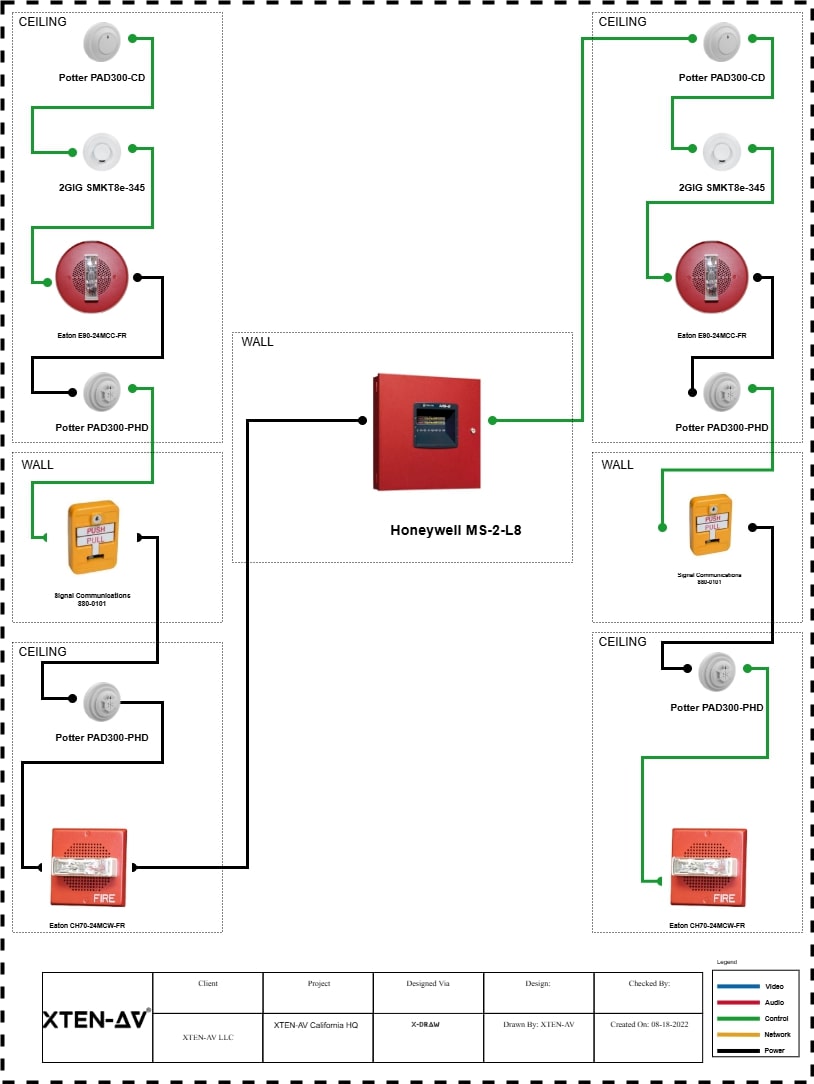
Step One: Understand System Requirements
Before starting the diagram, gather all relevant information about the building and the fire alarm system requirements. Consider factors such as building layout, occupancy type, fire codes, and required safety features. Identify whether the system will be conventional or addressable, as this affects device placement and wiring methods.
- Conventional Systems: Divide the building into zones, with each zone triggering the alarm as a whole.
- Addressable Systems: Each device communicates individually with the control panel, allowing precise identification of activated devices.
Understanding system requirements ensures that the diagram accurately reflects the intended functionality and coverage. Fire Alarm System Design Software often includes templates for both conventional and addressable systems, streamlining the initial setup.
Step Two: List All Devices and Components
Create a comprehensive inventory of all components in the fire alarm system. Typical devices include:
- Smoke and heat detectors
- Manual call points or pull stations
- Fire alarm control panels
- Notification appliances such as sirens, bells, or strobes
- Relays and auxiliary modules for integration with other building systems
- Power supply units and backup batteries
- Wiring and junction boxes
A complete list ensures that all necessary components are represented in the diagram and helps prevent omissions during installation.
Step Three: Choose a Diagram Method
Decide whether to create the diagram manually or using Fire Alarm System Design Software. While manual drawing can be useful for simple projects, software provides numerous advantages:
- Automatic placement of standard symbols for detectors, panels, and notification devices
- Built-in compliance checks for wiring, spacing, and code requirements
- Easier editing and version control
- Integration with building layout plans or BIM models
Using software ensures accuracy, consistency, and professional-quality diagrams suitable for client presentations and regulatory approvals.
Step Four: Plan Device Placement
Sketch the building layout, indicating rooms, corridors, and exit points. Determine where detectors, manual call points, and notification devices should be installed based on code requirements and occupancy type.
- Smoke detectors are generally placed on ceilings away from vents or areas with high airflow.
- Heat detectors are suitable for areas with dust, steam, or high ambient temperatures.
- Manual call points should be near exits and high-traffic areas for easy access.
- Audible and visual alarms must cover all occupied spaces effectively.
Proper planning ensures that the diagram will reflect accurate and effective system coverage.
Step Five: Draw the Control Panel Connections
Start connecting all devices to the fire alarm control panel in the diagram. For conventional systems, represent devices in zones and show the wiring routes for each zone. For addressable systems, include unique addresses for each device and indicate the communication loop.
- Use clear lines to represent wiring paths
- Label each connection to simplify installation and maintenance
- Include power supply connections and backup battery integration
Fire Alarm System Design Software can automatically generate wiring paths and zone layouts, reducing the risk of errors.
Step Six: Add Notification Devices and Relays
Include all audible and visual alarms, as well as relays for auxiliary systems. Show how these devices connect to the control panel or output modules. Indicate wiring routes, power sources, and any relays needed for long-distance or high-load devices.
- Ensure audible alarms meet required decibel levels throughout the building
- Place visual alarms in areas where occupants might not hear sound alerts
- Include relay connections for emergency lighting, HVAC shutdown, or sprinkler activation
Software can simulate alarm coverage and verify that devices are placed effectively for optimal safety.
Step Seven: Include Auxiliary and Safety Features
Add additional system components such as isolators, monitoring modules, and integration points with other safety systems. Clearly show how these elements connect to the main circuit.
- Isolators prevent wiring faults from affecting the entire system
- Monitoring modules allow remote supervision and fault detection
- Integration points ensure coordinated operation with sprinklers, elevators, or building management systems
Including these features in the diagram helps maintain system reliability and compliance.
Step Eight: Review and Validate the Diagram
After completing the diagram, review it carefully for accuracy and clarity. Verify that:
- All devices are included and correctly labeled
- Wiring paths are feasible and logical
- Zone layouts or address assignments are accurate
- Compliance with relevant fire codes and standards is maintained
Fire Alarm System Design Software often provides automated validation tools to identify missing connections, errors, or non-compliance issues.
Step Nine: Finalize and Document
Finalize the fire alarm diagram and prepare supporting documentation for installation and inspection:
- Device lists and specifications
- Wiring diagrams
- Zone tables or address lists for addressable systems
- Compliance and testing reports
Maintaining comprehensive documentation ensures smooth installation, simplifies maintenance, and provides records for future system upgrades or audits.
Conclusion
Creating a fire alarm diagram step by step is a critical process that ensures the system is accurate, compliant, and reliable. Proper planning, device placement, and clear wiring representation help engineers and integrators design systems that effectively protect occupants and property.
XTEN-AV emphasizes that Fire Alarm System Design Software can significantly streamline this process by providing automated tools, compliance checks, and professional-grade diagrams. Following a structured approach ensures the fire alarm system is safe, efficient, and ready for successful installation.
Comments