


Soldering is the backbone of modern electronics manufacturing, ensuring electrical connectivity, mechanical strength, and long-term reliability of electronic assemblies. Whether in consumer electronics, aerospace systems, or semiconductor packaging, the quality of each solder joint determines the performance and lifespan of the device. However, identifying a “good” solder joint involves far more than visual appearance—it requires an understanding of metallurgy, surface chemistry, and rigorous testing methods such as the solder joint reliability test.
This article provides a comprehensive exploration of what makes a solder joint reliable, how to inspect and test it, and the scientific principles behind its formation.
What Is a Solder Joint and Why Does It Matter?
A solder joint is the metallurgical bond formed when a filler metal (solder) is melted to join metallic surfaces. It provides both electrical continuity and mechanical strength between components and the printed circuit board (PCB).
In modern electronics, solder joints are subjected to thermal cycling, mechanical stress, and environmental exposure. The integrity of these joints is crucial—weak or defective solder joints can cause intermittent connections, device malfunction, or complete failure. That’s why manufacturers perform a solder joint reliability test to verify product durability before shipment.
What Determines the Quality of a Solder Joint?
Several factors influence solder joint quality, including:
- Wetting Ability: The solder must spread evenly over the pad and lead, forming a smooth interface without voids.
- Solder Composition: The alloy ratio (e.g., Sn63/Pb37 or SAC305) affects melting point and fatigue resistance.
- Surface Cleanliness: Oxidation or contamination prevents proper wetting.
- Temperature Profile: Reflow temperature and dwell time must be carefully controlled.
- Cooling Rate: Affects grain structure and intermetallic compound (IMC) formation.
Controlling these parameters ensures the formation of uniform joints capable of withstanding thermal and mechanical stress over time.
What Does a Good Solder Joint Look Like?
Visual inspection is the first step in assessing solder quality. A good solder joint typically displays the following characteristics:
- Smooth, shiny surface (for leaded solder) or slightly matte (for lead-free).
- Concave meniscus shape indicating proper wetting.
- No cracks, voids, or pinholes.
- No excessive solder or bridging.
- Proper alignment of component and pad.
Automated Optical Inspection (AOI) systems often use these visual parameters for initial quality checks before deeper solder joint reliability tests are performed.
What Are the Common Defects in Solder Joints?
Defects can originate from process errors, material issues, or design flaws. Common problems include:
- Cold Joint: Dull, grainy surface due to insufficient heat.
- Insufficient Wetting: Solder fails to adhere properly to one or both surfaces.
- Bridging: Solder connects adjacent leads, causing shorts.
- Voids: Gas entrapment inside the solder reduces thermal conductivity.
- Cracks: Occur from mechanical stress or poor thermal cycling performance.
- Head-in-Pillow (HiP): Poor contact between component ball and solder paste in BGA packages.
Each of these defects can reduce the long-term performance and must be identified early through inspection and solder joint reliability testing.
How Is Solder Joint Reliability Tested?
The solder joint reliability test encompasses a series of analytical and mechanical evaluations to determine a joint’s resistance to stress, temperature, and aging. These tests simulate real-world operating conditions.
Common reliability tests include:
- Thermal Cycling Test: Alternating high and low temperatures to measure fatigue resistance.
- Shear Test: Measures the mechanical strength of the joint under lateral force.
- Pull Test: Evaluates bond strength for wire or BGA solder balls.
- Vibration Test: Simulates mechanical stress from handling or transport.
- Temperature-Humidity-Bias (THB) Test: Checks corrosion and moisture-induced degradation.
- Microsection Analysis: Examines internal structure and IMC layer thickness under a microscope.
By conducting these solder joint reliability tests, manufacturers ensure that products can withstand the operational and environmental conditions they will face.
What Is the Role of Thermal Cycling in Solder Joint Reliability Tests?
Thermal cycling is among the most critical solder joint reliability tests. It exposes joints to repeated temperature changes, such as -40°C to +125°C, to replicate real-world thermal stress.
This test reveals how differences in thermal expansion between materials (like copper and silicon) create fatigue stress. Over time, micro-cracks may form within the solder or at the IMC interface. The number of cycles before failure is used as a quantitative measure of reliability.
Manufacturers such as Chengliankaida Technology Co., Ltd., which produce advanced vacuum soldering and semiconductor packaging systems, often use highly controlled reflow profiles to minimize voids and enhance fatigue life during such tests.
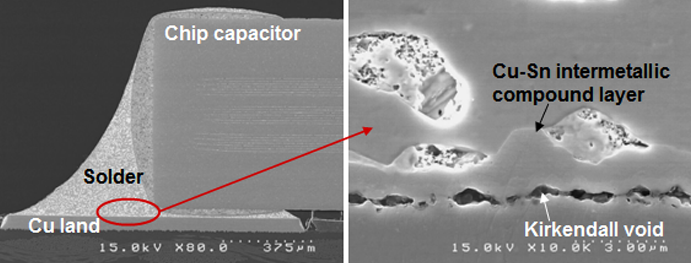
How Do Microstructure and IMC Formation Affect Reliability?
At the microscopic level, a solder joint consists of solder grains and intermetallic compounds (IMCs) formed at the interface between solder and substrate.
- Thin, uniform IMC layers promote good adhesion.
- Thick or brittle IMCs lead to cracking and poor fatigue performance.
The solder joint reliability test helps determine whether IMC growth remains within acceptable limits after thermal exposure. Advanced vacuum reflow and controlled atmosphere soldering—technologies developed by Chengliankaida Technology Co., Ltd.—help produce fine, uniform microstructures for enhanced durability.
How Is Void Rate Related to Solder Joint Reliability?
Voids are air or gas pockets trapped inside the solder joint. They reduce effective cross-sectional area, impair heat transfer, and concentrate stress, which can lead to early failure.
In power devices or high-current applications, voids can dramatically lower reliability. Manufacturers typically measure void rate through X-ray inspection and include it as part of the solder joint reliability test. Industry standards like IPC-A-610 specify acceptable void levels, usually below 25% for BGA and QFN components.
Minimizing voids requires proper solder paste formulation, optimized reflow profiles, and vacuum-assisted soldering processes.
How Do You Perform a Visual and Microscopic Inspection?
Visual inspection identifies surface-level defects, while microscopic inspection examines the joint’s internal structure.
Steps include:
- Visual Check: Look for cracks, bridges, or insufficient solder.
- X-ray Inspection: Detect hidden voids or misalignment in multilayer boards.
- Cross-section Analysis: Observe grain structure, IMC thickness, and void distribution.
These inspections complement the solder joint reliability tests, providing both qualitative and quantitative data for quality assurance.
What Standards Govern Solder Joint Reliability Testing?
To ensure consistency, international organizations have defined testing protocols. Key standards include:
- IPC-9701: Solder joint reliability test for surface mount components.
- JEDEC JESD22-A104: Temperature cycling procedures.
- MIL-STD-883: Microelectronics reliability standards.
- IEC 60068: Environmental testing for electronics.
Adhering to these standards ensures comparability and certification across global supply chains.
What Tools and Equipment Are Used in Solder Joint Reliability Testing?
Advanced testing equipment includes:
- Thermal shock chambers for rapid temperature changes.
- Shear and pull testers for mechanical evaluation.
- Scanning electron microscopes (SEM) for microstructure analysis.
- X-ray systems for non-destructive inspection.
- Data acquisition systems for monitoring during stress tests.
Integration of these tools enables comprehensive reliability assessment throughout the production cycle.
How Can Process Control Improve Solder Joint Reliability?
Reliability starts with process design. Parameters like solder paste quality, reflow temperature profile, and flux composition must be optimized.
Process control includes:
- Temperature Profiling: Ensures complete melting and controlled cooling.
- Flux Management: Prevents oxidation and improves wetting.
- Atmosphere Control: Using nitrogen or vacuum reflow reduces oxidation and void formation.
- Component Placement Accuracy: Prevents misalignment and stress concentration.
Consistent process control minimizes defects and improves solder joint reliability test outcomes.
What Are the Challenges in Modern Solder Joint Reliability?
As electronic devices become smaller and more powerful, solder joints face new challenges:
- Miniaturization: Finer pitch components increase difficulty in inspection.
- Lead-Free Transition: Lead-free alloys have higher melting points and different fatigue behaviors.
- Thermal Management: Power devices generate more heat, stressing joints.
- Mixed Material Assemblies: Different coefficients of thermal expansion complicate reliability.
Continuous innovation in materials and vacuum soldering equipment is essential to meet these challenges.
How Are Solder Joint Reliability Tests Evolving?
The industry is adopting more data-driven and accelerated reliability methodologies.
- Finite Element Modeling (FEM): Predicts stress distribution during thermal cycling.
- In-Situ Monitoring: Real-time resistance tracking during tests.
- Accelerated Life Testing: Reduces time-to-failure assessment.
- AI-Based Inspection: Uses machine learning for defect classification.
These advancements make the solder joint reliability test more predictive and less dependent on manual evaluation.
What Are Future Trends in Solder Joint Reliability Testing?
Emerging trends include:
- Vacuum and Low-Pressure Reflow: Eliminating voids for high-power modules.
- High-Temperature Alloys: For electric vehicles and aerospace applications.
- Nano-Reinforced Solders: Improved mechanical and thermal properties.
- Smart Testing Platforms: Integrating IoT sensors for predictive maintenance.
As manufacturing technologies advance, the solder joint reliability test will continue to evolve to meet the demands of next-generation electronics.
Conclusion
A good solder joint is more than a shiny surface—it’s a precisely engineered metallurgical bond capable of enduring years of mechanical and thermal stress. Identifying, testing, and improving solder joint reliability requires a combination of visual inspection, material science, and standardized testing methods.
Through rigorous solder joint reliability tests, manufacturers ensure that electronic devices perform consistently in all conditions. Companies like Chengliankaida Technology Co., Ltd. continue to innovate in vacuum soldering and semiconductor packaging technologies, contributing to higher reliability standards across the electronics industry.
Ultimately, understanding how to tell if a solder joint is good is fundamental to every stage of modern electronics manufacturing—from design to final quality assurance.
Comments